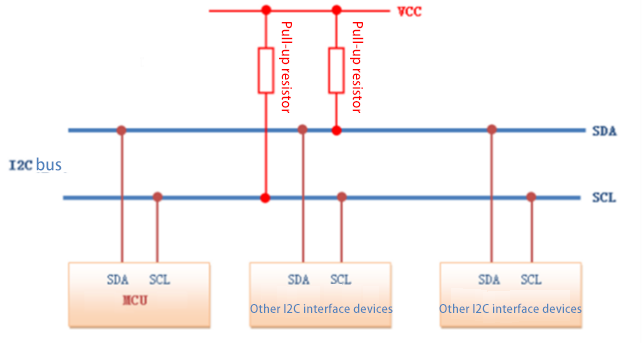
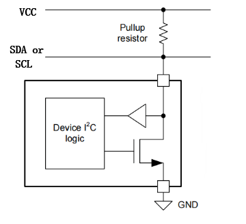
عندما نقوم بتصميم الدائرة الطرفية لواجهة IIC، فإننا عادةً ما نستخدم مخطط الطوبولوجيا مع مقاومة السحب لأعلى الموضحة في الشكل 1، وهيكلها الداخلي هو خرج المصرف المفتوح الموضح في الشكل 2.


يتم التحكم بمستوى خرج الدائرة المفتوحة بواسطة مقاومة سحب خارجية ومنطق داخلي، مما يسمح بخفض مستوى ناقل البيانات ثم تحريره. تتكون دائرة ناقل البيانات المفتوحة من ترانزستور NMOS، يتم تشغيله وإيقافه بواسطة إشارة تحكم. عندما تُشغّل إشارة التحكم ترانزستور NMOS، يكون الخرج منخفضًا. وعندما تُطفئ إشارة التحكم ترانزستور NMOS، يكون الخرج عائمًا، مما يتطلب مقاومة سحب خارجية لإخراج مستوى عالٍ.
يُتيح هذا التصميم لبوابة التصريف المفتوح التحكم بمرونة في مستوى ناقل البيانات مع تجنب تشغيله المباشر، مما يضمن اتصالاً آمناً بين الأجهزة المتعددة. وتتجلى مزايا استخدام هذا المخرج ذي التصريف المفتوح في الجوانب التالية:
1. منع حدوث قصر الدائرة
في حال استخدام تصميم الدفع والسحب بدلاً من تصميم التصريف المفتوح، وتوصيل عدة أجهزة بنفس ناقل البيانات، وإخراج منفذ إدخال/إخراج في أحد الأجهزة إشارة عالية بينما يُخرج منفذ إدخال/إخراج في جهاز آخر إشارة منخفضة، سيحدث تماس كهربائي بين توصيلات VCC وGND لهذين المنفذين، مما يُسبب تلفًا في الدائرة. أما تصميم التصريف المفتوح فيُزيل هذه المشكلة. وبغض النظر عن عدد الأجهزة المتصلة بناقل البيانات، فلا يوجد خطر حدوث تماس كهربائي.
2. زيادة قدرة القيادة وتقليل استهلاك الطاقة
يُتيح توصيل مقاومة سحب لأعلى بطرف خرج التصريف إمكانية تغيير مستوى الجهد، مما يُعزز قدرة القيادة. ويستفيد هذا من قدرة القيادة للدائرة الخارجية لتقليل قدرة القيادة الداخلية للدائرة المتكاملة. فعندما يكون ترانزستور MOSFET الداخلي في الدائرة المتكاملة قيد التشغيل، يتدفق تيار القيادة من مصدر الطاقة الخارجي (VCC) عبر مقاومة السحب لأعلى، ثم إلى ترانزستور MOSFET، وصولًا إلى الأرضي (GND). ولا يتطلب الأمر سوى تيار قيادة بوابة صغير داخل الدائرة المتكاملة.
3. استخدم "Wired AND" لتحديد حالة نشاط الناقل
يمكن توصيل عدة دبابيس إخراج مفتوحة التصريف بخط واحد لتشكيل علاقة منطقية "و"، تُعرف بوظيفة "و السلكية". عندما ينخفض مستوى أي دبوس، يصبح مستوى المنطق على خط التصريف المفتوح صفرًا. هذا هو المبدأ نفسه الذي تستخدمه ناقلة I2C لتحديد حالة نشاط الناقلة.
4. تسهيل تغيير مستوى الإخراج
يمكن تغيير مستوى الإرسال عن طريق تغيير جهد مصدر الطاقة للسحب لأعلى، بينما يتم تحديد مستوى الإخراج العالي بواسطة VDD.

Xml سياسة الخصوصية المدونة خريطة الموقع
حقوق النشر
@ شركة مايكرو ماجيك كل الحقوق محفوظة.
 دعم الشبكة
