التحليل الفني لميل جهاز قياس الميل: قياس دقيق، مستقر وموثوق
Jun 13, 2025
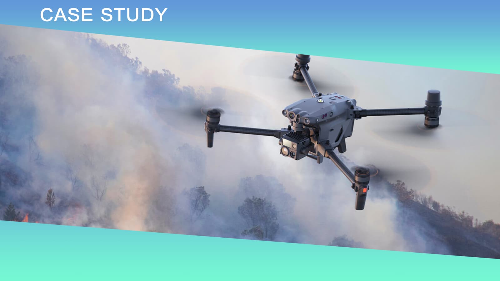
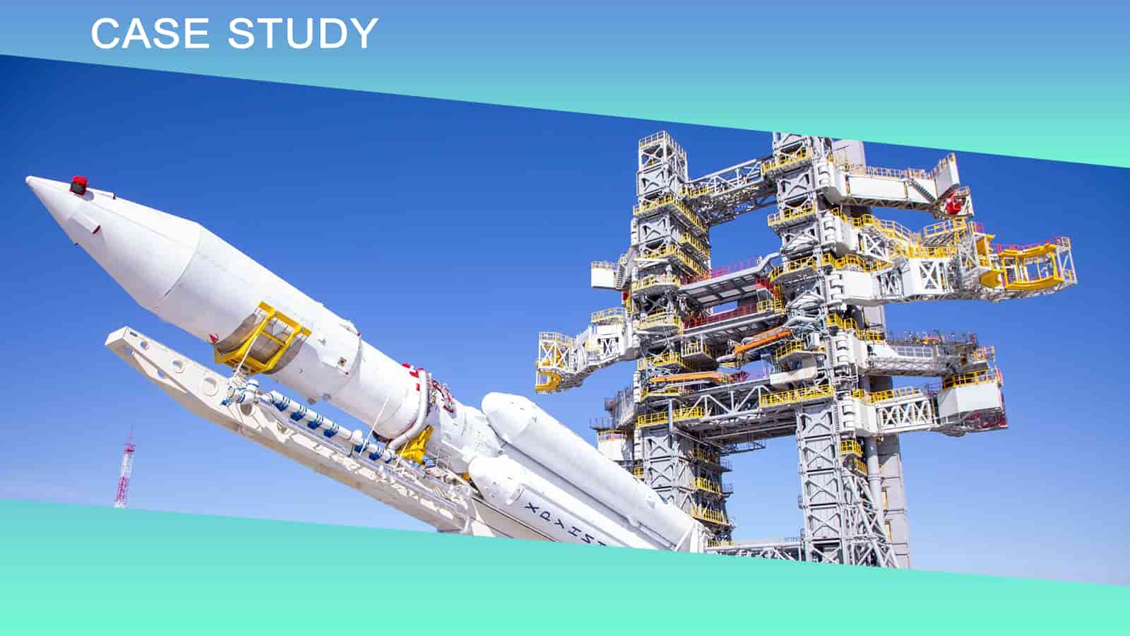
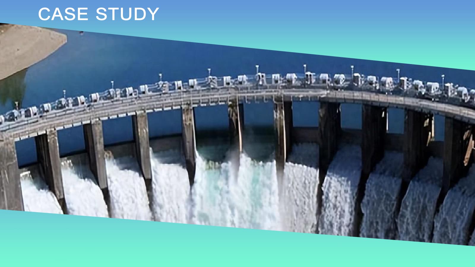
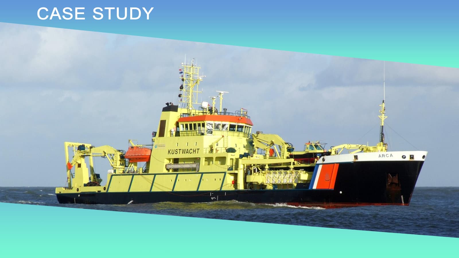
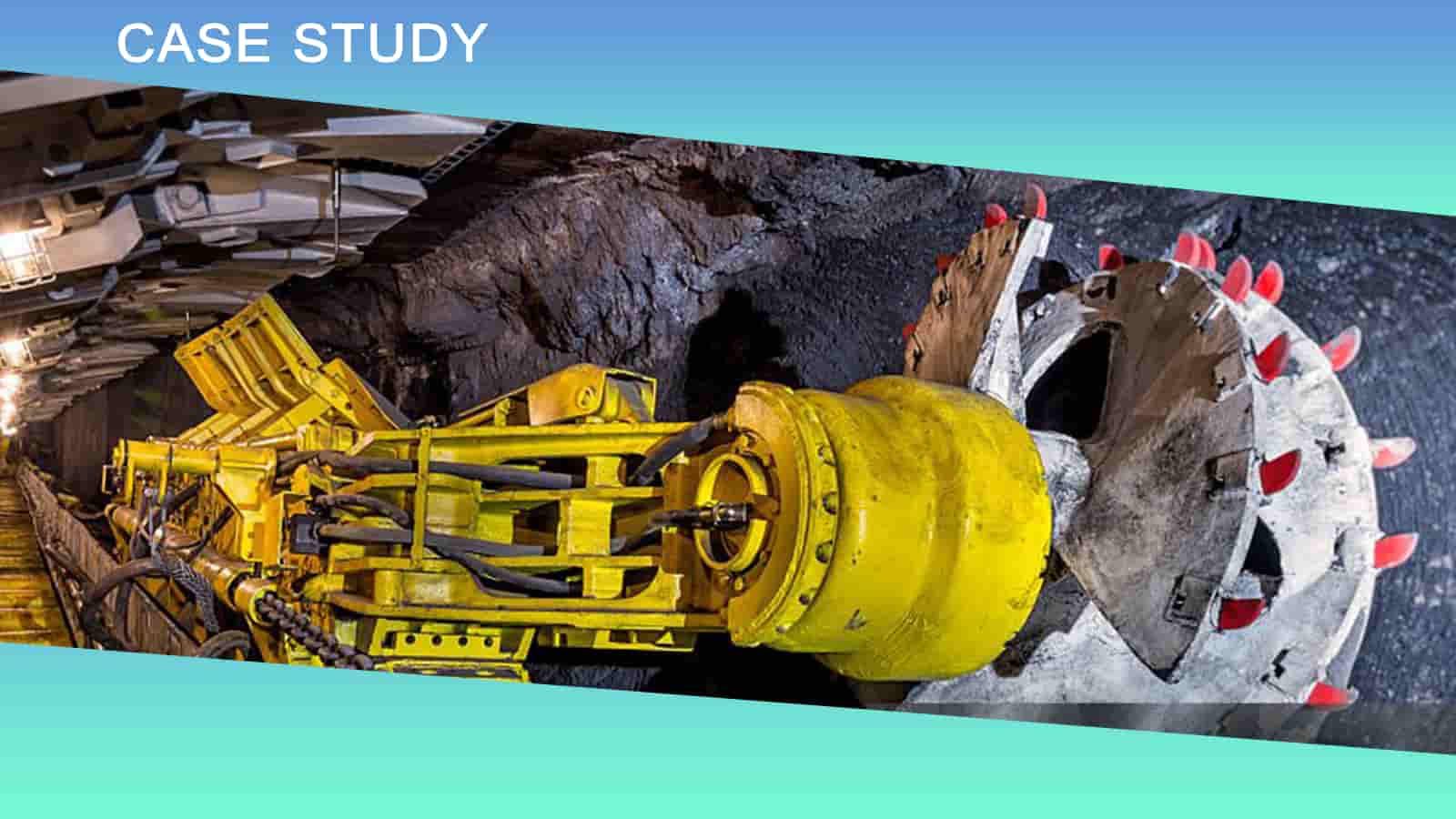
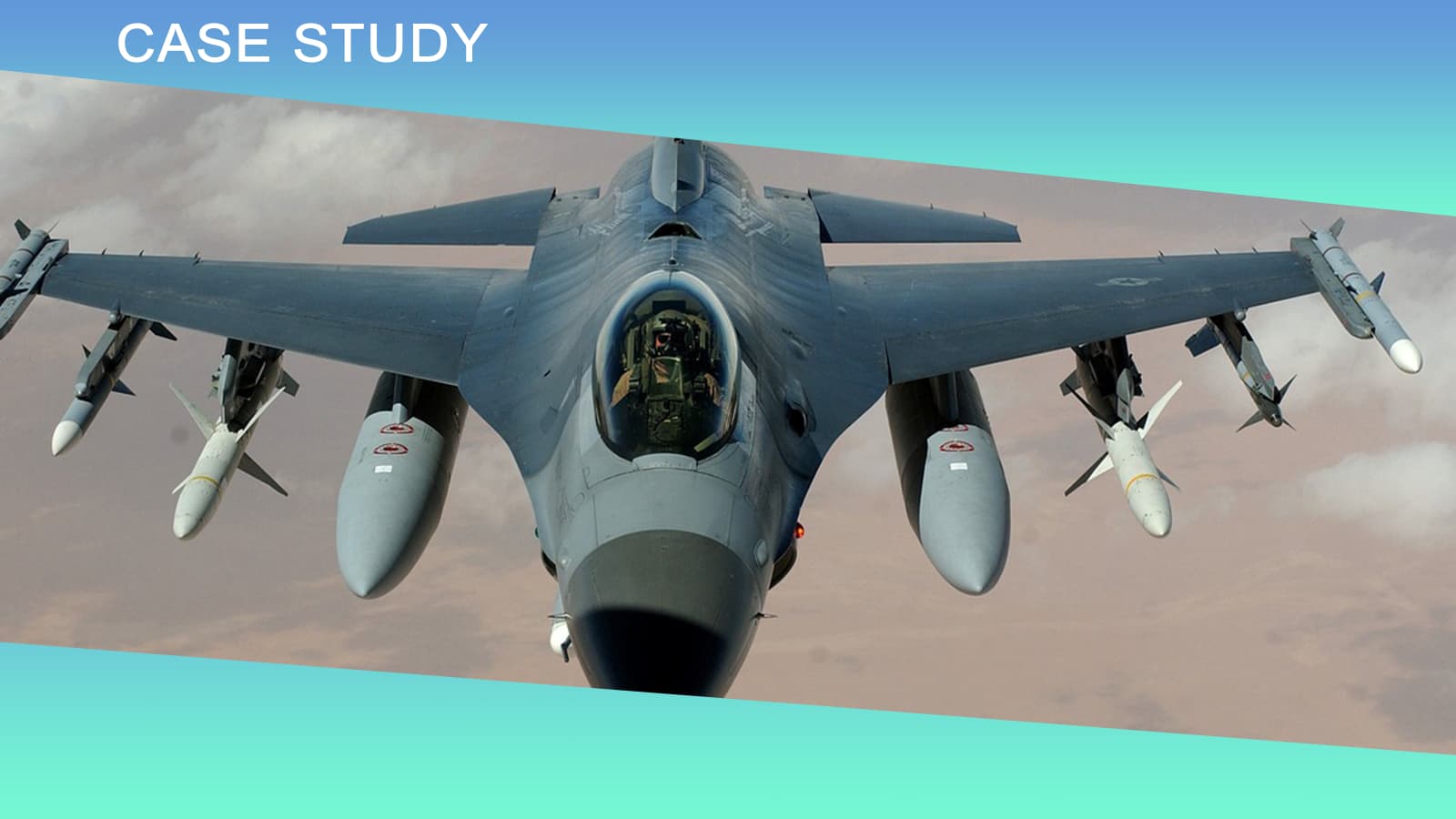
اكتشف التكنولوجيا المتقدمة وراء أجهزة استشعار الميل الإلكترونية (مقياس الميل)، ومبادئ عملها، ومزاياها، وتطبيقاتها، واتجاهاتها المستقبلية. مثالية للأتمتة الصناعية، والبناء، والفضاء، وغيرها. مقدمة: أهمية قياس الميل في مجالات الأتمتة الصناعية الحديثة، وهندسة الإنشاءات، والفضاء، والاستكشاف الجيولوجي، تلعب تقنية قياس الميل دورًا حاسمًا. فسواءً تعلق الأمر بضبط وضعية المعدات الميكانيكية الضخمة، أو مراقبة تشوهات هياكل المباني، أو التحكم في استقرار طيران الطائرات بدون طيار، فإن بيانات الميل الدقيقة تُعدّ أساسًا لضمان التشغيل الآمن والفعال للأنظمة.يُعدّ جهاز قياس الميل الإلكتروني (Tilt) أداةً أساسيةً في مجال قياس الزوايا. وبفضل دقته العالية، وثباته، وميزاته الرقمية، فإنه يحلّ تدريجياً محلّ أدوات قياس الزوايا الميكانيكية التقليدية، وأصبح الخيار المفضل في مجال القياسات الصناعية. مبدأ عمل مقياس الميل الإلكتروني يعتمد المبدأ الأساسي لجهاز قياس الميل الإلكتروني على مستشعرات التسارع بتقنية الأنظمة الكهروميكانيكية الدقيقة (MEMS) أو تقنية استشعار السعة السائلة. فعندما يميل الجهاز، يستشعر المستشعر التغيرات في مركبات تسارع الجاذبية على طول كل محور، ومن خلال خوارزميات محددة، يحسب زاوية ميل الجهاز بالنسبة للمستوى الأفقي. لنأخذ مقياس الميل ثلاثي المحاور بتقنية MEMS كمثال. يمكن وصف مبدأ عمله بإيجاز كما يلي:1. يتم استخدام ثلاثة مقاييس تسارع متعامدة لقياس مكونات الجاذبية على طول المحاور X و Y و Z على التوالي.2. يتم حساب زوايا الميل في كل اتجاه باستخدام الدوال المثلثية.3. يتم التخلص من التداخل البيئي من خلال تعويض درجة الحرارة وخوارزميات الترشيح.4. يتم إخراج إشارات مقياس الميل الرقمي عالي الدقة. المزايا التقنية لمقياس الميل الإلكتروني بالمقارنة مع أجهزة قياس الميل الميكانيكية التقليدية، تتمتع أجهزة قياس الميل الإلكترونية بالمزايا الهامة التالية: 1. قياس عالي الدقة: يمكن لأجهزة قياس الميل الإلكترونية الحديثة أن تحقق دقة تصل إلى 0.01 درجة، مما يلبي متطلبات الدقة لمعظم التطبيقات الصناعية. 2. المخرج الرقمي: يقوم بإخراج الإشارات الرقمية مباشرة، مما يسهل التكامل مع وحدات التحكم المنطقية القابلة للبرمجة (PLCs) وأجهزة الكمبيوتر الصناعية للتحكم وغيرها من المعدات الآلية، ويبسط بنية النظام. 3. قدرة القياس متعددة المحاور: يمكنها قياس زاوية الميل وزاوية الدوران وحتى زاوية الانعراج في وقت واحد، مما يوفر معلومات شاملة عن الوضع. 4. قدرة قوية على مقاومة التداخل: بفضل خوارزميات الترشيح وآليات تعويض درجة الحرارة، يمكنه مقاومة الاضطرابات البيئية بشكل فعال مثل الاهتزازات وتغيرات درجة الحرارة. 5. الحجم الصغير: باستخدام تقنية MEMS، يتم تقليل حجم المستشعر بشكل كبير، مما يجعله مناسبًا بشكل خاص للتطبيقات ذات المساحة المحدودة. سيناريوهات التطبيق النموذجية بفضل أدائه المتميز، تم تطبيق مقياس الميل الإلكتروني على نطاق واسع في مختلف المجالات: 1. مجال هندسة الإنشاءات- مراقبة صحة الهياكل الإنشائية واسعة النطاق- مراقبة تشوه البنية التحتية مثل الجسور والسدود- التحكم في وضعية معدات البناء مثل الرافعات البرجية والمصاعد 2. الأتمتة الصناعية- التحكم في مستوى الآلات الهندسية- معايرة معدات خطوط الإنتاج الآلية- التحكم في تحديد مواقع معدات التخزين والخدمات اللوجستية 3. الفضاء الجوي- وضعية الطيران المستقرة للطائرات بدون طيار- التوجيه الاتجاهي للألواح الشمسية للأقمار الصناعية- نظام مساعدة الهبوط للطائرات 4. الاستكشاف الجيولوجي- مراقبة زاوية ميل معدات الحفر- نظام إنذار مبكر للانهيارات الأرضية- إرشادات لمدّ خطوط الأنابيب تحت الأرض التحديات والحلول التقنية على الرغم من أن تقنية مقياس الميل الإلكتروني ناضجة تماماً، إلا أنها لا تزال تواجه بعض التحديات في التطبيقات العملية: 1. مشكلة انحراف درجة الحرارةقد تؤدي تغيرات درجة الحرارة إلى انحراف نقطة الصفر للمستشعر، مما يؤثر على دقة القياس. تستخدم أجهزة قياس الميل الإلكترونية الحديثة خوارزميات تعويض درجة الحرارة وتصحيحات مستشعر درجة الحرارة في الوقت الفعلي لتقليل تأثير درجة الحرارة. 2. تداخل الاهتزازاتيمكن أن تُولّد الاهتزازات الميكانيكية في بيئة العمل إشارات تداخل إضافية ناتجة عن التسارع. وتشمل الحلول ما يلي:- تطبيق تصميم التخميد الميكانيكي على الأجهزة- تطبيق خوارزميات الترشيح الرقمي على البرنامج- اختيار مستشعرات سعوية سائلة ذات أداء أفضل في مقاومة الاهتزاز 3. خطأ في التثبيتقد يؤدي عدم استواء سطح تركيب المستشعر إلى أخطاء منهجية. يوفر مقياس الميل الإلكتروني المتطور وظيفة معايرة التركيب، مما يُمكّن من التخلص من أخطاء التركيب من خلال عملية معايرة بسيطة. اتجاهات التنمية المستقبلية مع الانتشار الواسع لتقنيات الثورة الصناعية الرابعة وإنترنت الأشياء، تتطور تقنية مقياس الميل الإلكتروني في الاتجاهات التالية: 1. تكامل أعلى: إن دمج وظائف قياس الميل ومعالجة البيانات والاتصال اللاسلكي على شريحة واحدة يتيح تصميمًا أكثر إحكامًا. 2. الذكاء: مزود بخوارزميات الذكاء الاصطناعي، يمكنه إجراء التشخيص الذاتي والمعايرة الذاتية والتكيف مع البيئة. 3. الاتصال اللاسلكي: باستخدام تقنيات بلوتوث منخفضة الطاقة، و LoRa وغيرها من التقنيات اللاسلكية، يسهل نشرها في السيناريوهات التي يصعب فيها التوصيل السلكي. 4. دمج أجهزة الاستشعار المتعددة: من خلال دمج أجهزة الاستشعار مثل الجيروسكوبات ومقاييس المغناطيسية، فإنه يوفر معلومات أكثر شمولاً عن الوضع. خاتمة يشهد مقياس الميل الإلكتروني، باعتباره مكونًا أساسيًا في القياسات الصناعية الحديثة، تطورات تكنولوجية سريعة. سواءً كان ذلك في أعمال البناء في الموقع، أو التحكم في وضعية المعدات الدقيقة، أو مراقبة سلامة البنية التحتية، فإن مقياس الميل الإلكتروني يلعب دورًا حاسمًا في الخلفية.عند اختيار جهاز قياس الميل الإلكتروني المناسب، يُنصح بمراعاة عوامل مثل نطاق القياس، ودقة القياس، وملاءمة الجهاز للظروف البيئية، وواجهة الإخراج. في حالات التطبيقات الخاصة، يمكن النظر في حلول مُخصصة لتحقيق أفضل نتائج القياس. تُقدم شركة مايكرو ماجيك الأدوات والدعم الفني لمشاريع الطيران والفضاء، وحفر المناجم، وغيرها من المشاريع الهندسية. تشمل سلسلة البوصلات الإلكترونية الحالية منتجات مثل T700-I وT7000-B، والتي تتميز بوظائف تعويض مغناطيسي ناعم وصلب، مما يُسهم بشكل كبير في تحسين دقة توجيه البوصلة.T700-Iمهما كانت احتياجاتك، فإن مايكرو ماجيك بجانبك.T7000-Bمهما كانت احتياجاتك، فإن مايكرو ماجيك بجانبك.T7000-Jمهما كانت احتياجاتك، فإن مايكرو ماجيك بجانبك.


 الشبكة المدعومة


 بالعربية