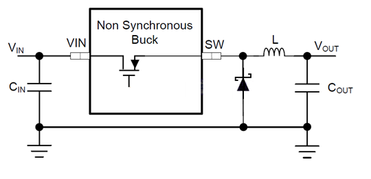
 الشكل 1. مخطط محول BUCK غير المتزامن
يوضح الشكل 1 بنية محول باك غير المتزامن. عادةً ما تدمج رقائق محول باك غير المتزامن ترانزستور MOSFET عالي الجهد داخليًا فقط. يلزم تركيب صمام ثنائي حر بين طرف SW والأرضي (GND) كمسار حر لملف الحث عند إيقاف تشغيل ترانزستور MOSFET عالي الجهد.
يجب أن يستوفي اختيار الصمام الثنائي الحر على الأقل المعيارين الصارمين التاليين (1)(2) ومعياري التحسين التاليين (3)(4):
(1) يجب أن يكون جهد التشغيل العكسي VRRM للثنائي الحر مساويًا أو أكبر من جهد الإدخال الأقصى VIN(max).
(2) يجب ألا يقل تيار التوصيل الأمامي IF(AV) للدايود الحر عن Iout(max)*(1-D)، حيث D هي دورة تشغيل محول الجهد الخافض، وIout(max) هو أقصى تيار حمل يمكن أن يتحمله محول الجهد الخافض. ولتحديد قدرة الدايود الحر على تحمل التيار الزائد بدقة أكبر، يمكن اختياره ليكون أكبر من أو يساوي ذروة التيار على المحث IOUT+(ΔIL)/2.
(3) كلما قلّ انخفاض الجهد الأمامي VF، قلّ فقد الطاقة الناتج عن هذا العامل، وزادت كفاءة الطاقة. (4) كلما زادت سرعة التبديل من حالة التشغيل إلى حالة الإيقاف (أي كلما قلّ زمن الاسترداد العكسي trr)، قلّ فقد الاسترداد العكسي، وزادت كفاءة الطاقة، كان ذلك أفضل.
تعتبر ثنائيات حاجز شوتكي (SBDs) خيارات مثالية لثنائيات التحرر نظرًا لانخفاض الجهد الأمامي الصغير ووقت الاسترداد العكسي السريع (عادةً عشرات النانوثانية أو حتى بضع نانوثانية)، مما يقلل من فقد الطاقة في ثنائي التحرر.
لتصميم محول تيار مستمر خافض للجهد بنطاق جهد دخل يتراوح بين 9 و36 فولت، وجهد دخل نموذجي 12 فولت، وجهد خرج 5 فولت، وسعة حمل قصوى 5 أمبير، تم اختيار ثنائي شوتكي بجهد تشغيل عكسي 40 فولت وتيار أمامي أكبر من 5 أمبير، وذلك لأن جهد دخله الأقصى هو 36 فولت. كما هو موضح في الشكل 2، يتميز ثنائي شوتكي SS54 بجهد تشغيل عكسي 40 فولت، وتيار تقويم متوسط 5 أمبير، وانخفاض جهد أمامي أقصى 0.55 فولت عند تيار أمامي 5.0 أمبير، مما يفي بمتطلبات الدائرة.
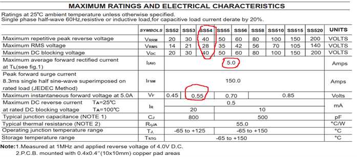 الشكل 2: المعلمات الكهربائية لثنائي شوتكي SS54
عندما يكون جهد الدخل 12 فولتًا، تكون دورة التشغيل 5/12، ويبلغ متوسط التيار المار عبر الصمام الثنائي 5.0 أمبير × (1 - 5/12) = 2.917 أمبير. وعندما يكون جهد الدخل 36 فولتًا، تكون دورة التشغيل 5/36، ويبلغ متوسط التيار المار عبر الصمام الثنائي 5.0 أمبير × (1 - 5/36) = 4.3 أمبير. كما هو موضح في الشكل 3، يُعد الصمام الثنائي D3 (SS54) في مثال تصميم دائرة TPS54360DDAR هو الصمام الثنائي المُختار للحماية من التيار الزائد.
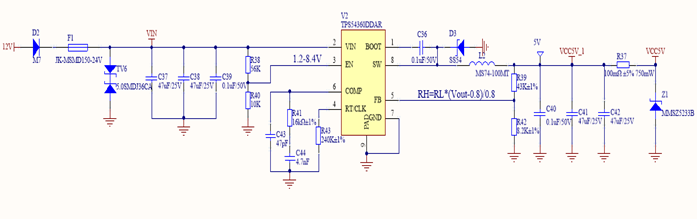 الشكل 3. مثال على تصميم دائرة TPS54360DDAR

Xml سياسة الخصوصية مدونة خريطة الموقع
حقوق الطبع والنشر @ شركة مايكرو ماجيك جميع الحقوق محفوظة.
 الشبكة المدعومة


 بالعربية