تيار البدء هو تيار عابر وعالي الارتفاع يتولد عند تشغيل مصدر الطاقة أو الجهاز. في مصادر الطاقة والأنظمة الإلكترونية، يُعد تيار البدء غير مرغوب فيه لأنه قد يُسبب إجهادًا زائدًا للجهاز وتلفه.
تستخدم دوائر إمداد الطاقة من نوع Buck دائرة بدء تشغيل تدريجي للتحكم في معدل ارتفاع التيار أثناء بدء تشغيل النظام، مما يوفر الطاقة تدريجيًا للحمل ويقلل من تأثير تيار البدء المفاجئ على النظام. وتتحقق وظيفة بدء التشغيل التدريجي في إمداد الطاقة Buck من خلال ضبط مكثف بدء التشغيل التدريجي. يؤدي ذلك إلى كبح تيار البدء المفاجئ بشكل فعال، ومنع تيار شحن مكثف الخرج من تجاوز حد تيار إمداد الطاقة أثناء بدء التشغيل. يقلل هذا من ارتفاع التيار المفاجئ على دائرة التبديل نفسها والأحمال المتصلة بها، ويقلل من انخفاضات جهد الدخل. علاوة على ذلك، يضمن ضبط وقت بدء التشغيل التدريجي بشكل صحيح ارتفاعًا سلسًا لجهد الخرج، مما يمنع حدوث أي تقلبات.

لنأخذ شريحة TPS54561DPRT من شركة TI كمثال. يظهر مخططها الوظيفي الداخلي في الشكل 1. تُنفذ شريحة TPS54561DPRT خاصية البدء التدريجي عن طريق توصيل مكثف خارجي بدبوس SS/TR.
تُعبّر العلاقة بين الفولت والأمبير للمكثف عن طريق المعادلة I = C * dV / dt. لذا، كلما زادت سعة المكثف، ارتفع الجهد، وكلما قصر زمن الشحن، زاد تيار الشحن. بعبارة أخرى، بالنسبة لسعة معينة، يتناسب مقدار تيار شحن المكثف طرديًا مع معدل تغير الجهد.
يُطبّق جهاز تزويد الطاقة ذو التبديل الخافض النموذجي زمن بدء تشغيل ناعم قابل للضبط عن طريق توصيل مكثف بدء تشغيل ناعم خارجي (CSS) بدبوس بدء التشغيل الناعم (SS). يقوم مصدر تيار الشحن الداخلي لبدء التشغيل الناعم (ISS) بشحن مكثف بدء التشغيل الناعم (CSS) ثم يقارنه بالجهد المرجعي (VREF) لتحديد نهاية عملية بدء التشغيل الناعم. وفقًا لمعادلة شحن المكثف I = C * ΔV / ΔT، فإن الزمن TSS اللازم لشحن جهد مكثف بدء التشغيل الناعم من الصفر إلى VREF هو:
TSS_SET = CSS * VREF / ISS (المعادلة 1)
في دائرة محول خافض للجهد، بافتراض أن جهد الخرج المطلوب هو VOUT، وسعة مكثف الخرج هي COUT، وتيار بدء الشحن لمكثف الخرج هو IINRUSH، فإن الزمن اللازم لارتفاع جهد مكثف الخرج (أي جهد الخرج) من الصفر إلى جهد الخرج المطلوب هو TSS_OUT. باستخدام معادلة شحن المكثف، نحصل على:
TSS_OUT = COUT * VOUT / IINRUSH (المعادلة 2)
يشترط لبدء تشغيل مصدر طاقة تبديلي أن يتم شحن جهد مكثف بدء التشغيل التدريجي من الصفر إلى الجهد المرجعي (VREF) خلال فترة بدء التشغيل التدريجي (TSS_SET)، وأن يتم شحن جهد مكثف الخرج من الصفر إلى القيمة المحددة (VOUT) خلال نفس الفترة الزمنية. وبالتالي، نحصل على:
TSS_SET = TSS_OUT (المعادلة 3)
الصيغة النهائية لحساب مكثف بدء التشغيل التدريجي هي:
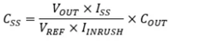 (المعادلة 4)
عند بدء تشغيل محول التبديل، يُشار عادةً إلى التيار الذي يشحن مكثف الخرج بتيار البدء، IINRUSH. ويتراوح هذا التيار عادةً بين 5% و10% من تيار الحمل الأقصى لمحول التبديل، IOUT,MAX. إذا كان تيار البدء، IINRUSH، يساوي 5% من تيار الخرج الأقصى لمصدر طاقة التبديل، IOUT,MAX، فإن IINRUSH = 5% × IOUT. وبالتعويض عن IINRUSH = 5% × IOUTMAX في المعادلة 4، نحصل على التعبير التالي لمكثف بدء التشغيل التدريجي، CSS:
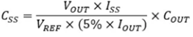 (المعادلة 5)
على سبيل المثال، باستخدام شريحة TPS54561DPRT، تكون بيانات الحساب الفعلية كما يلي:
المتطلبات: VOUT = 5.0 فولت، COUT = 3 * 47 ميكروفاراد = 141 ميكروفاراد، IOUT,MAX = 5.0 أمبير
المعلمات: ISS = 1.7 ميكرو أمبير، VREF = 0.8 فولت، IINRUSH = 5% * 5.0 أمبير = 0.25 أمبير
نتائج الحساب:
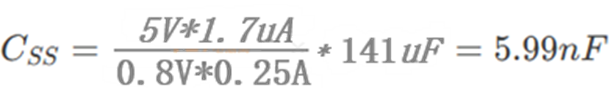
يُستخدم مكثف قياسي سعته قريبة من 10 نانوفاراد. وهذا هو السبب في أن قيمة C13 تساوي 0.01 ميكروفاراد في الشكل أدناه.

يُعدّ ضبط مكثفات بدء التشغيل التدريجي خطوةً أساسيةً في كبح تيار البدء وضمان استقرار النظام. باختيار سعة المكثف المناسبة، يمكنك حماية المكونات مع تلبية متطلبات بدء التشغيل في مختلف السيناريوهات.

Xml سياسة الخصوصية مدونة خريطة الموقع
حقوق الطبع والنشر @ شركة مايكرو ماجيك جميع الحقوق محفوظة.
 الشبكة المدعومة


 بالعربية