بناء جهاز تحديد اتجاه الشمال المصغر عالي الدقة بتقنية MEMS
Dec 23, 2024
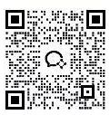
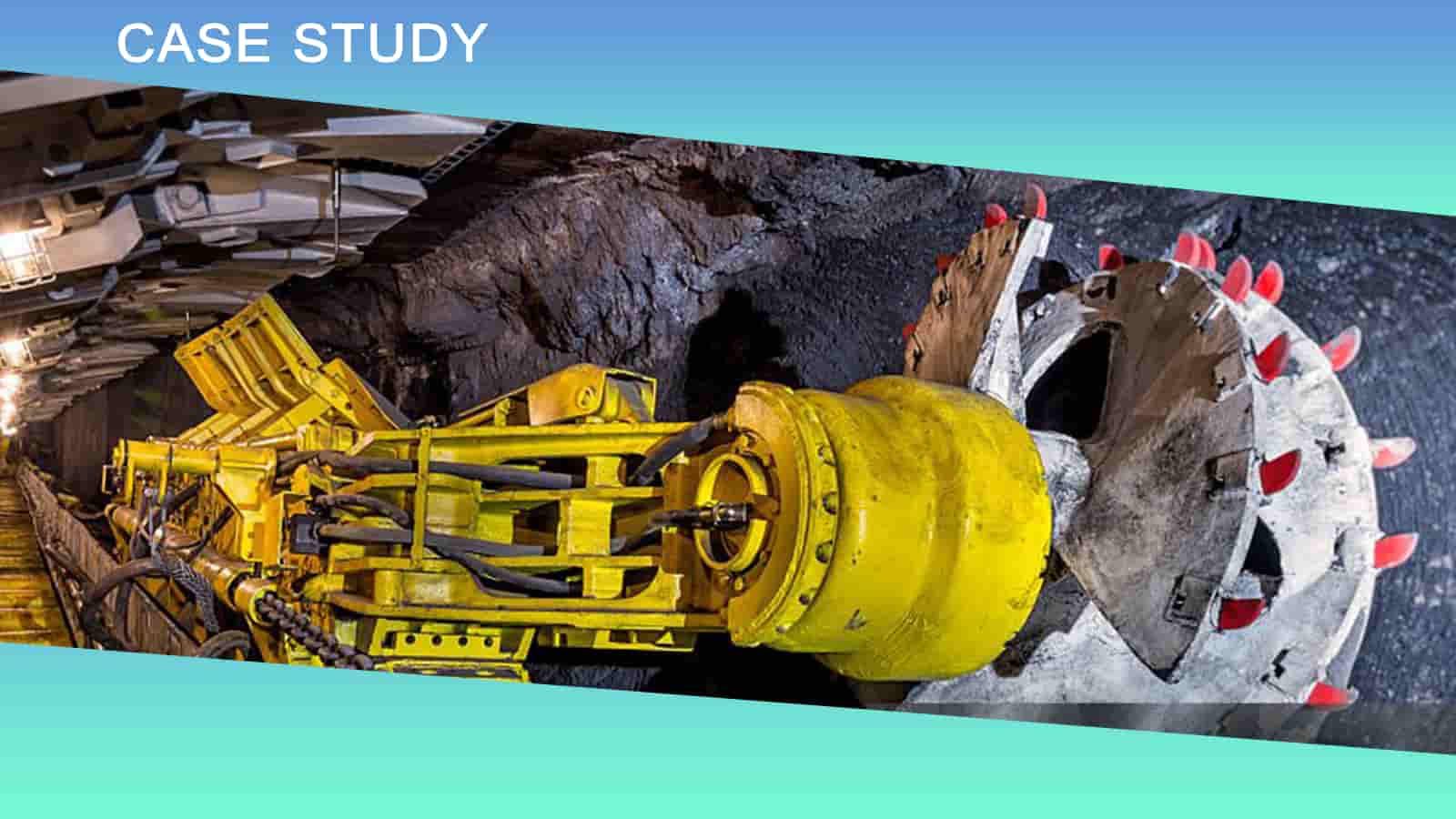
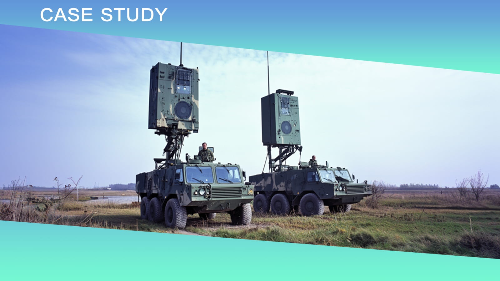
النقاط الرئيسيةالمنتج: جهاز تحديد اتجاه الشمال المصغر عالي الدقة بتقنية MEMSالميزات الرئيسية:المكونات: وحدة قياس القصور الذاتي (IMU) مع جيروسكوب MEMS ثلاثي المحاور ومقياس تسارع، بالإضافة إلى دوائر الطاقة والتحكم والعرض.الوظيفة: توفير اتجاه دقيق بشكل مستقل، دون أن يتأثر بالأقمار الصناعية أو الأحوال الجوية.التطبيقات: يستخدم في التعدين، واستخراج النفط، والسفن، والأنفاق.الملاحة بالقصور الذاتي: تقيس الموقع والسرعة والتسارع باستخدام الجيروسكوبات ومقاييس التسارع.الخلاصة: يتطور تصميم جهاز تحديد المواقع الشمالية بتقنية MEMS، حيث تتكيف نماذج مثل NF1000 مع الأشكال الأسطوانية للصناعات المتخصصة مثل تسجيل بيانات البترول.يُعدّ جهاز تحديد الشمال أداةً لقياس الزاوية بين الشمال والشمال الحقيقي، حيث يوفر معلومات دقيقة عن الاتجاه والوضع في بيئة ثابتة، ويلعب دورًا هامًا في مجالات التعدين، واستخراج النفط، ومعدات السفن، وحفر الأنفاق، وغيرها. في الوقت الحاضر، تتزايد متطلبات دقة وحجم أجهزة تحديد الشمال في مختلف القطاعات، مما أدى إلى تطويرها لتصبح أكثر دقةً وتصغيرًا.في البداية، سأبدأ من وجهة النظر الأساسية، مع التركيز على تكوين نظام البحث عن الشمال، حتى يتمكن الجميع من فهم جهاز البحث عن الشمال بشكل أوضح.المكونات الأساسية للباحث عن الشماليُمكن لجهاز تحديد اتجاه الشمال بتقنية MEMS تزويد الجسم المتحرك بمعلومات الاتجاه بشكل مستقل تمامًا، دون الاعتماد على الأقمار الصناعية، ولا يتأثر بالظروف المناخية، ولا يتطلب عمليات معقدة. فهو لا يوفر فقط واجهة إخراج البيانات للحاسوب، بل يوفر أيضًا واجهة تفاعلية سهلة الاستخدام بين الإنسان والآلة.يتكون جهاز تحديد الشمال بتقنية MEMS بشكل أساسي من وحدة قياس القصور الذاتي (IMU) وجزء الدائرة، ويُوضح الشكل 1 مخطط مكوناته. تتكون وحدة قياس القصور الذاتي (IMU) من جيروسكوب وآلية دوران. أما جزء الدائرة فيتكون بشكل رئيسي من أربع لوحات دوائر، تشمل: لوحة الطاقة، ولوحة التحكم، ولوحة مكبر الطاقة، واللوحة الأساسية. يوضح الجدول 1 مكونات نظام تحديد الشمال.الشكل 1: مخطط كتلي للأجهزة الخاصة بالباحث الشماليالجدول 1: مكونات الباحث عن الشماليوجد مؤشران على لوحة جهاز تحديد الشمال بتقنية MEMS: مؤشر تحديد الشمال ومؤشر مصدر الطاقة؛ زران: زر الشمال ومفتاح الطاقة؛ شاشة عرض رقمية مكونة من سبعة أجزاء وخمسة أرقام؛ مصهر؛ يتم توصيل الجهاز خارجيًا بموصلين: مقبس الطاقة ومقبس واجهة الاتصال.يتكون نظام تحديد الشمال من وحدات قياس بالقصور الذاتي وخوارزميات، وهو نفس مبدأ نظام الملاحة بالقصور الذاتي، مع اختلاف أن الخوارزميات المختلفة تُشكل أنظمة مختلفة. لذا، فإن نظام تحديد الشمال هو أيضاً نظام ملاحة بالقصور الذاتي.يمكن لنظام الملاحة بالقصور الذاتي قياس معلومات الموقع والسرعة اللحظية والتسارع والسرعة الزاوية من خلال مكونات القياس بالقصور الذاتي دون تدخل من البيئة الخارجية، ودون إشعاع وبشكل سري، ويمكنه توفير معلومات مستمرة عن الموقع وزاوية الوضع والسرعة الخطية والسرعة الزاوية وغيرها من معلومات المعلمات في مجالات الطيران والفضاء والملاحة والمجالات العسكرية.يوضح الشكل 2 المبدأ الأساسي للملاحة بالقصور الذاتي. نظام الإحداثيات الموضح في الشكل هو oxy، حيث يمثل (x,y) الموضع اللحظي. على منصة نظام الملاحة بالقصور الذاتي، تُحسب السرعة Vx وVy والموضع اللحظي x وy باستخدام الحاسوب، حيث يتحكم المحوران x وy في محوري قياس مقياسَي التسارع على التوالي، ويُستخدم مقياس التسارع لقياس تسارع هذين المحورين.الشكل 2: المبدأ الأساسي للملاحة بالقصور الذاتيفي نظام الملاحة بالقصور الذاتي، يُعتبر سطح الأرض كرويًا، وبالتالي يتم تمثيل موقع المتجه بخط الطول وخط العرض، وإذا كان المحوران x و y يشيران إلى الشمال والشرق على التوالي، فإن موقع المتجه يتم تمثيله بخط الطول وخط العرض:حيث R هو نصف قطر الأرض؛ φ0 – خط العرض الأولي للحامل؛ λ0 – خط الطول الأولي للحامل؛φ – الموقع الجغرافي لخط العرض للناقل؛ λ – الموقع الجغرافي لخط الطول للناقل؛vx – السرعة المتجهة شمالاً؛ vy – السرعة المتجهة شرقاً.تتكون وحدة القياس بالقصور الذاتي، والتي تُسمى أيضًا وحدة الملاحة بالقصور الذاتي، من مقياس تسارع وجيروسكوب. يتألف نظام الملاحة بالقصور الذاتي من ثلاثة أجزاء: وحدة القياس بالقصور الذاتي، والحاسوب، وشاشة العرض. يقيس مقياس التسارع تسارع الطائرة المتحركة في ثلاثة اتجاهات (عرضي، طولي، ورأسي)، بينما يقيس الجيروسكوب، ذو درجات الحرية الثلاث، دوران الطائرة في ثلاثة اتجاهات (طولي ورأسي). يحسب الحاسوب سرعة الطائرة وموقعها، وتعرض شاشة العرض جميع بيانات معلومات الملاحة.خاتمةمعظم أجهزة تحديد الشمال مكعبة الشكل، ولكن مع تزايد الطلب عليها في مختلف الصناعات، يتغير شكلها أيضًا. على سبيل المثال، جهاز NF1000، المصمم خصيصًا لتسجيل بيانات النفط والحفر الموجه والتعدين، شهد تطورًا كبيرًا في شكله، إذ تحول من مكعب إلى أسطوانة تتناسب تمامًا مع شكل المجس. ولأنه جهاز تحديد شمال بتقنية MEMS، فهو مزود بجيروسكوب MEMS ثلاثي المحاور ومقياس تسارع MEMS ثلاثي المحاور.آمل أن تتمكن من خلال هذه المقالة من فهم بنية جهاز تحديد الشمال المصغر عالي الدقة بتقنية MEMS، وإذا كنت مهتمًا بمعرفة المزيد عن أجهزة تحديد الشمال، فيرجى الاتصال بنا. NF1000نظام الملاحة بالقصور الذاتي عالي الأداء، نظام MEMS ديناميكي، باحث عن الشمال


 الشبكة المدعومة


 بالعربية