
Introduction
The core components of an Inertial Navigation System (INS)—gyroscopes and accelerometers—are highly sensitive to the vibration environment of the host platform. Vibration can induce additional drift in gyroscopes and increase output errors in accelerometers; in severe cases, it may even cause the entire system to fail. Consequently, the integration of vibration isolators has become an essential aspect of INS design. Their primary function is to establish physical isolation between the platform’s vibrations and the inertial sensors, effectively attenuating high-frequency vibrations to ensure that the INS continues to provide high-precision navigation data, even under complex operating conditions.
Structure and Principles of Vibration Isolators
Basic Configuration
An INS vibration isolator is essentially a spring-damper unit. Taking the common four-point mounting configuration as an example, each isolator consists of the following components:
Rubber damping pads (one on top and one on the bottom): These provide elasticity and damping, serving as the core elements for vibration isolation.
Metal limiting sleeves: These constrain the compression of the rubber pads, preventing damage from overloading.
Metal shims: These transmit fastening force and work in conjunction with the limiting sleeves to control the degree of pre-compression.
Mounting screws: These secure the entire assembly to the mounting surface of the host platform.
During installation, as the screws are tightened, the metal shims move downward until they reach the limiting shoulder, inducing a controlled amount of pre-compression in the upper and lower rubber damping pads. This level of compression directly influences the stiffness and natural frequency of the isolator, making it a critical process parameter for performance control.
Mechanical Model
A single vibration isolator can be simplified as a single-degree-of-freedom (SDOF) spring-damper-mass system, the vibration transmission characteristics of which can be described by a transmissibility coefficient, η:
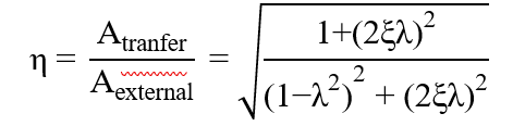
Where:
"A_transfer" is the vibration amplitude transmitted to the device; "A_external" is the amplitude of the external excitation vibration.
λ = ω/ω_n: Frequency ratio, where ω is the excitation frequency and ω_n is the natural frequency of the system.
ξ = c/(2√mk): Damping ratio, where c is the damping coefficient, k is the stiffness, and m is the mass.
When λ ≈ 1, the system enters resonance, and the transmissibility η reaches a peak value of η_max ≈ 1/(2ξ); in this state, vibration is amplified rather than attenuated. When λ > √2, η < 1, and the vibration isolator enters the effective isolation range; a larger λ results in better isolation performance. Beyond λ > 5, the rate of attenuation levels off; in engineering practice, λ is typically selected in the range of 2.5 to 4.5.
Vibration isolation efficiency α is defined as: α = (1 - η) × 100%.
Design Objectives
The design of an inertial navigation system (INS) vibration isolation system must meet the following requirements: The natural frequency ω_n is typically designed to be between 50–60 Hz, ensuring that the low-frequency vibrations of the carrier (2–200 Hz) fall within the effective isolation range. A damping ratio ξ of approximately 0.1 (corresponding to a loss factor β ≈ 0.2) is chosen to balance the suppression of resonance peaks with efficiency in the isolation range. Equal stiffness in all three axes (X, Y, and Z) is required to ensure balanced isolation performance across these directions and to prevent angular vibration coupling.
Taking a vehicle-mounted inertial navigation system as an example: by selecting a frequency ratio λ = 2.5 and an isolation frequency of 150 Hz, the resulting natural frequency f_n is 60 Hz, with a damping ratio ξ = 0.10, a transmissibility η = 0.195, and a vibration isolation efficiency α = 80.5%.
Material Selection
Comparison of Common Materials
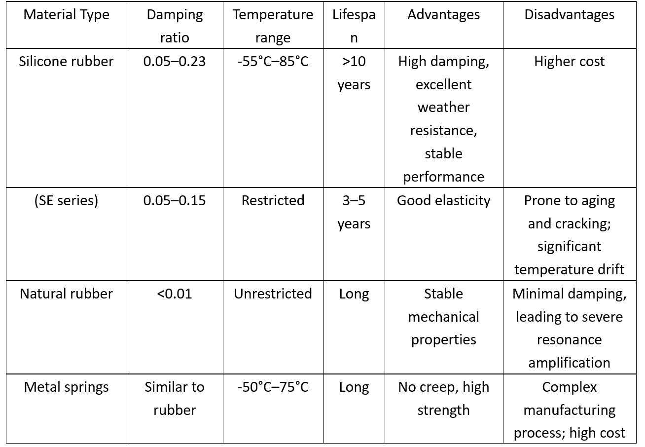
Materials for inertial navigation vibration isolators must balance four key factors: elasticity, damping, environmental adaptability, and service life. Mainstream solutions include:
Selection Principles
For standard airborne or vehicle-mounted inertial navigation systems (INS), silicone rubber is the preferred choice. It offers distinct advantages, including high damping, stability across a wide temperature range, and a long service life; for instance, the domestically produced SE-series silicone rubber vibration isolators can achieve a vibration isolation efficiency of over 90%. For extreme environments—such as those encountered in space or involving rapid, high-to-low temperature cycling—metal rubber or damping alloys are more suitable. The inertial navigation system of the Mars rover, for example, utilizes metal rubber vibration isolators capable of operating across a temperature range of -50°C to 75°C, while providing over 80% attenuation against shocks exceeding 1,000 G. For high-precision attitude measurement applications, damping alloys are superior to rubber; their high stiffness and minimal creep prevent deformation of attitude angles (maintaining an error of less than 30 arcseconds).
Optimization Strategy
Research and practical experience indicate that, while maintaining necessary structural strength, one should select rubber materials with a lower Shore hardness. Additionally, increasing the height of the damping pad and the difference between its inner and outer diameters helps lower the natural frequency and enhance vibration-damping efficiency.
Verification of Vibration-Damping Performance
The vibration-damping performance for inertial navigation systems (INS) is verified through sinusoidal sweep vibration testing. By analyzing the resulting amplitude-frequency characteristic curves (transmissibility vs. frequency), the following are evaluated:
Whether the resonant frequency lies outside the operational frequency range.
Whether the resonant amplification factor meets specified requirements (typically < 5–6 dB).
Whether the -3 dB bandwidth covers the target frequency range for vibration isolation.
Experimental results for an INS vibration-damping system in a drone showed a resonant frequency of 55 Hz, a maximum acceleration transmissibility of 2.2 (approximately 6.8 dB), and a -3 dB bandwidth of 30–40 Hz—all meeting the design specifications. Following the implementation of the damping system, the standard deviation of the gyroscope output was reduced to 34.6%–43.5% of its original value, confirming the system's effectiveness.
Conclusion
Built-in INS vibration dampers utilize a spring-damping mechanism to effectively attenuate vibrations from the host platform along the transmission path. The core of the design lies in the optimal balancing of the natural frequency and damping ratio, ensuring that the operational frequency range falls within the vibration-isolation zone (where the transmissibility ratio $\lambda > \sqrt{2}$) while simultaneously suppressing resonant peaks. In terms of materials, silicone rubber is the mainstream choice due to its comprehensive advantages, whereas metal rubber and damping alloys serve indispensable roles in extreme environments. A well-designed vibration-damping system can attenuate vibration interference by 70%–90%, providing a robust mechanical foundation for high-precision output from inertial navigation systems.
ترك رسالة
امسح ضوئيًا إلى WeChat :