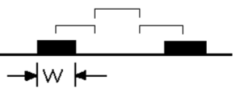
To ensure signal routing quality and prevent crosstalk during PCB design, we maintain a spacing of three times the line width between signal traces. As shown in Figure 1, this spacing refers to the center-to-center spacing of the traces. Because line width is expressed in English as "width," this rule is often referred to as the 3W principle. When the center-to-center spacing of traces is at least three times the line width, 70% of the inter-line electric fields are guaranteed to be free of interference. If 98% of the inter-line electric fields need to be free of interference, the 10W rule can be used.
 The 3W principle is a PCB layout principle that designers can adhere to without requiring additional design techniques. However, this design approach consumes significant area and can make routing more difficult. The fundamental starting point for the 3W principle is to minimize coupling between traces. This principle can be expressed as follows: the distance between traces (the distance between trace centers) must be three times the width of a single trace. Alternatively, the distance between two traces must be greater than twice the width of a single trace. For example, if a clock line is 6 mil wide, other traces can only be routed 2 x 6 mils away from this trace, or the edge-to-edge spacing must be greater than 12 mils. The 3W principle is easily implemented in PCB design by ensuring that the center-to-center spacing between traces is three times the trace width. For example, if a trace is 6 mil wide, then in Allegro, the line-to-line rule can be set to 12 mils to meet the 3W principle. The spacing in the software is calculated based on the edge-to-edge spacing, as shown in Figure 2.


Xml سياسة الخصوصية المدونة خريطة الموقع
حقوق النشر
@ شركة مايكرو ماجيك كل الحقوق محفوظة.
 دعم الشبكة
