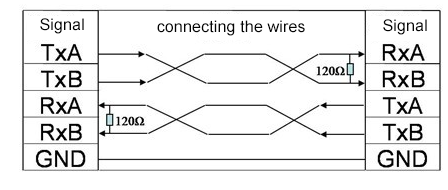
(1) RS422 working mode: RS422 supports full-duplex communication mode, that is, data can be transmitted bidirectionally at the same time, that is, two pairs of differential lines are used for sending and receiving respectively, which improves the efficiency and flexibility of communication.
(2) Signal level: RS422 uses differential signal to transmit data, that is, two signal lines (one is a positive signal line and the other is a negative signal line) are used to transmit data. It has strong anti-interference ability and can achieve long-distance and high-speed communication. Its differential signal level standard is as follows:
① Transmitter: When transmitting logic "1", the voltage difference between line A and line B is +2V to +6V; when transmitting logic "0", the voltage difference between line A and line B is -2V to -6V.
② Receiving end: It can recognize differential voltages as low as ±200mV. When the voltage of line A is higher than the voltage of line B by more than 200mV, it is recognized as logic "1"; when the voltage of line A is lower than the voltage of line B by more than 200mV, it is recognized as logic "0".
(3) Transmission distance: At 115200 baud rate, the maximum transmission distance of RS485 is usually about 1200 meters. Usually the baud rate is inversely proportional to the transmission distance, but the actual distance may vary due to the following factors:
① Transmission line quality: High-quality shielded twisted pair can reduce signal attenuation and interference and extend the transmission distance;
② Electromagnetic environment interference: An environment with strong electromagnetic interference will shorten the transmission distance;
③ Terminal matching resistance: Correctly installing the terminal resistance (usually 120 ohms) can reduce signal reflection, ensure signal integrity, and improve communication quality. If a longer distance is required, consider reducing the baud rate or using a repeater.
(4) Load capacity of the transmitter: One RS422 driver can drive up to 10 receivers.
(5) Connection method of terminal matching resistor: RS422 can be connected without terminal matching resistor when the distance is short (generally not more than 300 meters). When communicating over long distances, a 120 ohm resistor can be connected at the end of the signal receiving end as the terminal resistor. The terminal resistor can absorb the reflected waves on the network and effectively enhance the signal strength.

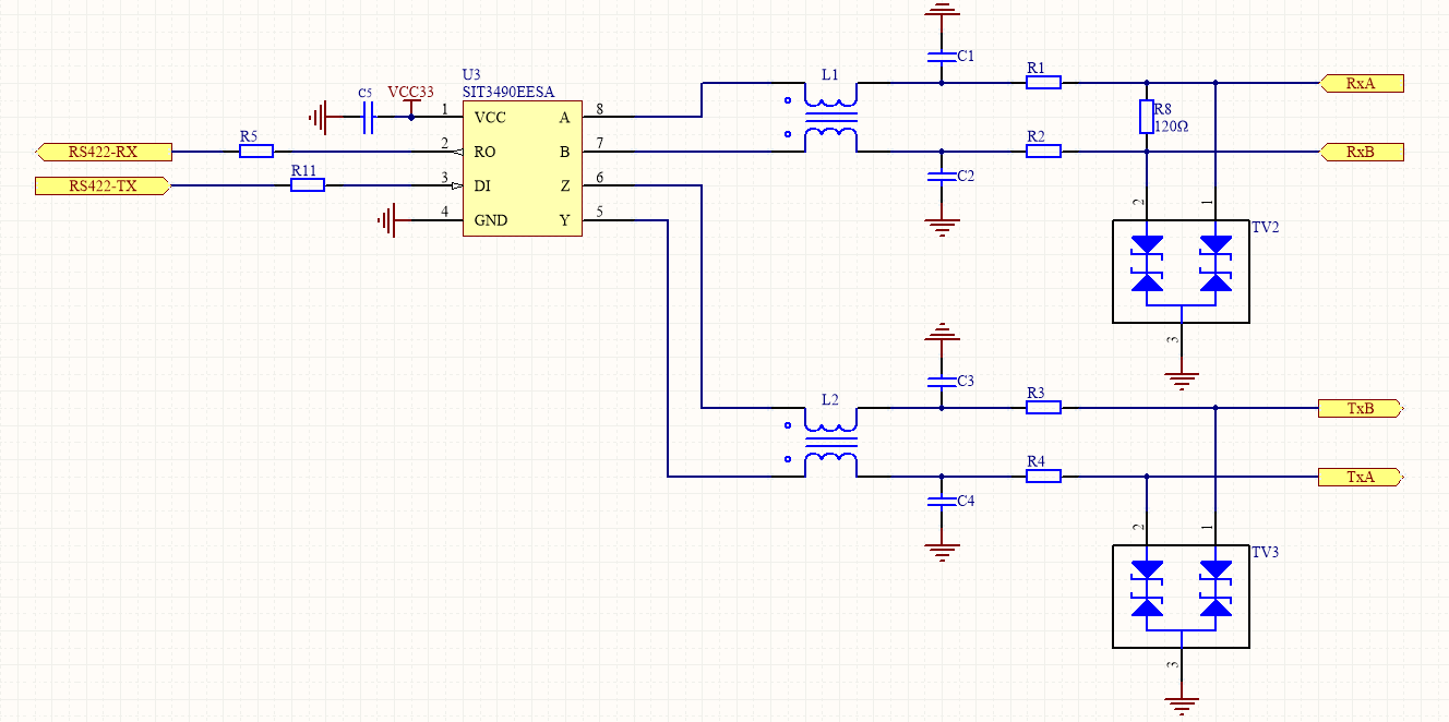
(6) Protection of RS422 circuit and suppression of interference: Generally, anti-static (ESD) protection, current limiting protection and suppression of common mode noise are required. The electrical principle is shown in the figure below:

Anti-static (ESD) protection: Connect TVS diodes to the ground on the A and B differential lines respectively to prevent static crosstalk to the subsequent circuit and damage to components.
Current limiting protection: Connect a small resistance resistor in series on the A and B differential lines to prevent the signal line from short-circuiting or overcurrent from damaging the interface chip.
Suppression of common mode noise: Connect common mode chokes L1 and L2 in series on the A and B differential lines to suppress common mode interference on the line and improve the anti-interference ability of the system. The common mode inductor impedance selection range is 120Ω/100MHz~2200Ω/100MHz, and the typical value is 1000Ω/100MHz.
The sending and receiving A and B differential lines are connected to the ground and connected to capacitors to provide a low-impedance return path for interference to suppress common-mode high-frequency noise. The capacitance value selection range is 22PF~1000pF, and the typical value is 100pF.
(1) RS422 signal lines cannot be routed together with strong power lines, and the principle of separation of strong and weak electricity must be followed.
(2) The correct connection method of signal lines and ground lines, the A and B lines of the sending end are connected to the A and B lines of the receiving end, and the ground line must also be connected. The signal ground can be an additional unshielded twisted pair or the shielding layer of a shielded twisted pair. The RS422 bus must be reliably grounded at a single point, that is, there can only be one point grounded on the entire RS422 bus, not multiple points, because the reason for grounding is to keep the voltage on the ground wire (usually the shielded wire is used as the ground wire) consistent to prevent common mode interference. If multiple points are grounded, it will be counterproductive.
(3) Signal interference causes unstable communication and solutions: If there is sometimes no communication connection on site, this may be that the signal is interfered with, thus affecting the continuity of the signal. This requires the use of shielded twisted pair cables for long-distance transmission, and a 120-ohm impedance matching resistor is connected in parallel at the receiving terminal.
(4) Selection of shielded cable: Choose to use ordinary Category 5e shielded twisted pair cables, i.e. network cables.
|
Problem |
Possible cause |
Solution |
|
Communication failure |
Wrong line |
connection Ensure A+ and B- are correctly connected
|
|
Data loss |
Transmission distance is too long or rate is too high |
Reduce baud rate or use relay amplifier |
|
Severe interference |
Electromagnetic interference |
Use shielded twisted pair and ensure good grounding
|
|
Signal reflection |
No terminal matching |
Add 120Ω terminal resistor at the end of the bus |
|
Multi-device communication abnormality |
Exceeding the maximum number of receiving devices |
Reduce the number of receiving terminals or use RS-485 instead |

Xml سياسة الخصوصية المدونة خريطة الموقع
حقوق النشر
@ شركة مايكرو ماجيك كل الحقوق محفوظة.
 دعم الشبكة
